


Vol. 1 Technical Guide
Secrets of
Anchoring Systems
The definitive guide to the design, layout, and installation of yacht and ship anchoring systems. Original content by John Muir.

Table of Contents
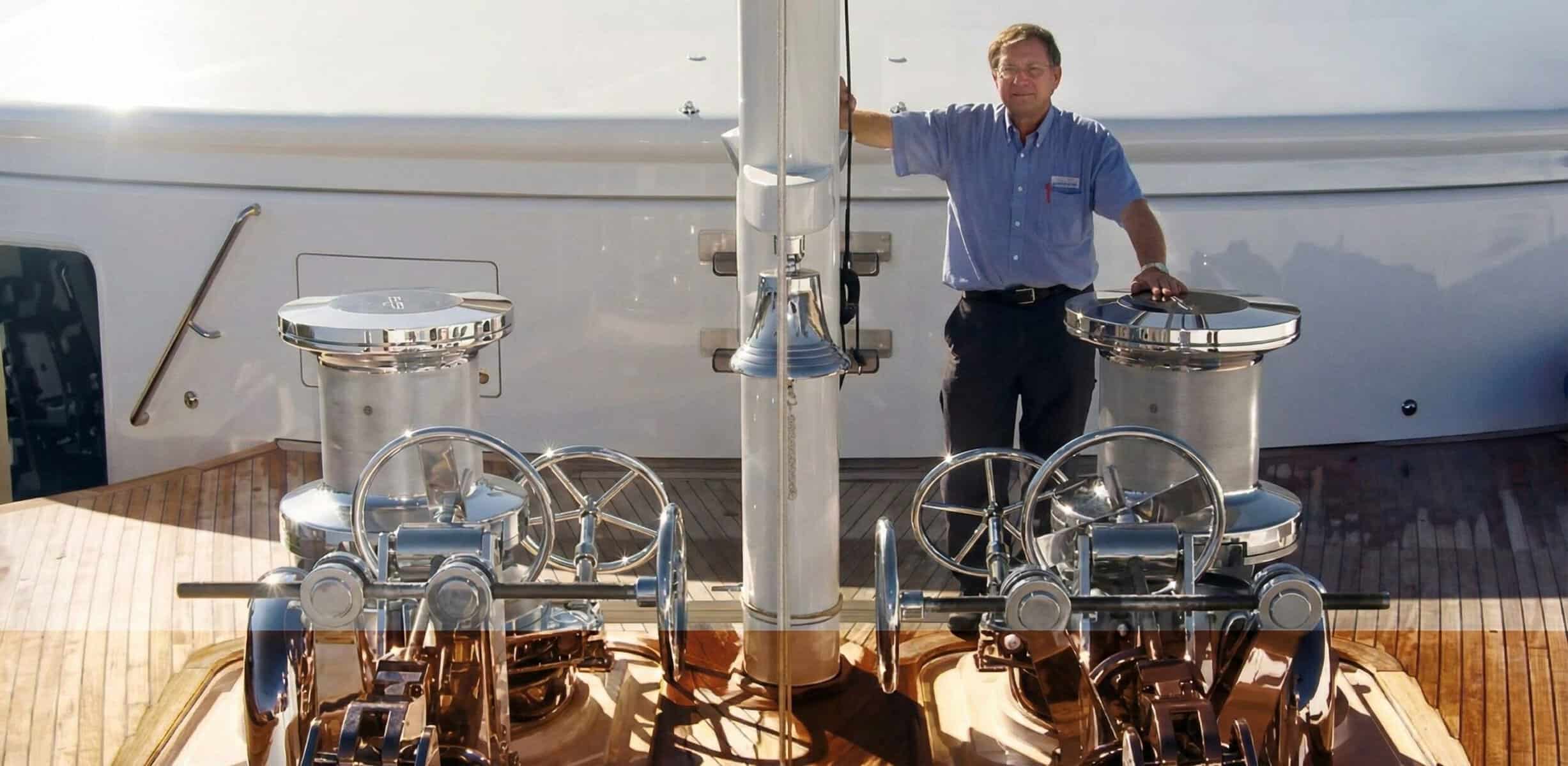
ROBERT JOHN MUIR
ROBERT JOHN MUIR (KNOWN BY ALL AS JOHN), WAS BORN IN 1944 IN HOBART ON A LITTLE-KNOWN AUSTRALIAN ISLAND CALLED TASMANIA. GROWING UP IN THE SEAFARER’S SUBURB OF BATTERY POINT, DOWN THE ROAD FROM THE “SHIPWRIGHT’S ARMS” HOTEL, JOHN WAS DESTINED FOR A CAREER IN THE MARINE INDUSTRY.
HAILING FROM A FAMILY OF SAILORS AND SHIP BUILDERS FAMOUS FOR THE CONSTRUCTION OF SYDNEY TO HOBART CHAMPION YACHT WESTWARD, JOHN STARTED HIS CAREER AS A MARINE DIESEL FITTER WHERE HE LEARNED THE VALUES OF HARD WORK AND RESILIENCE.
IN 1968, MUIR DIESEL SERVICES WAS FOUNDED ON THE SHORELINE OF THE DERWENT RIVER DOWN THE ROAD FROM HIS FAMILY HOME, AND IT WAS HERE, NEXT TO HIS FATHER’S BOAT BUILDING BUSINESS, THAT JOHN DEVELOPED THE VERY FIRST MUIR ANCHOR WINCHES. THE ADVICE FROM HIS FATHER JOCK WOULD PROVE PIVOTAL IN BUILDING HIS NEW BUSINESS’ REPUTATION:
WITHIN 3 YEARS, MUIR WAS RENAMED MUIR ENGINEERING, THE NAME IT STILL OFFICIALLY CARRIES TO THIS DAY, AND OVER THE COURSE OF THE NEXT 45 YEARS, JOHN AND HIS TEAM BUILT A FORMIDABLE REPUTATION ON THE BACK OF AN INCREDIBLE WORK ETHIC AND AN UNWAVERING COMMITMENT TO INNOVATION, QUALITY AND SERVICE.
2023 MARKS THE 55TH YEAR SINCE JOHN FOUNDED MUIR, AND TO THIS DAY, DESPITE THE TRIALS AND TRIBULATIONS OF CHANGING YACHT DESIGNS, NEW COMPETITORS, EVOLVING TECHNOLOGIES AND CHALLENGING MARKETS, MUIR REMAINS THE LEADING GLOBAL SUPPLIER OF ANCHORING AND MOORING SYSTEMS.

“MAKE SURE THE WINCH YOU DESIGN AND BUILD IS STRONGER THAN THE DECK IT’S BOLTED DOWN TO.”
IT TRULY IS A TESTAMENT TO A MAN WHO STARTED FROM SCRATCH, DEFIED THE ODDS AND BUILT AN INTERNATIONALLY SUCCESSFUL BUSINESS IN THE SPITE OF ALL OBSTACLES.
THESE GUIDEBOOKS ARE DEDICATED TO JOHN.
WHY PUBLISH THIS GUIDE?
At Muir, we believe that anchoring systems play a crucial role in delivering a safe and enjoyable boating experience. In our 55 years innovating, crafting, installing and commissioning custom anchoring systems on board over 2000 vessels for yards all around the world, we’ve learned a thing or two about ensuring they work as they should. It starts with designing an aligned anchoring island and locker, and then placing equipment in the right place, followed by employing the correct techniques during install and, finally, checking critical measurements meet specification during commissioning. If you ignore these steps, it doesn’t matter which anchoring system you buy and install, it simply will not work as it should.
This booklet gives you (a yard, designer, architect, construction contractor… whoever!!) the tips you need to develop a design, install and commissioning approach that will, if the equipment is fit for purpose, deliver an anchoring system that deploys and retrieves your ground tackle as smooth as silk.
That means safer anchoring, happier captains and crew members, less warranty claims, reduced wear and tear and, most importantly, a satisfied owner - surely things we can all agree are common goals, and the reasons why we developed this book.
| Item | Terms | Descrition |
|---|---|---|
| 1 | Windlass | Equipment that lowers and raises the anchor and chain. Also commonly called Anchoring winch. |
| 2 | Chain Stopper | Engaged when the vessel is at anchor to take the load off the windlass. Encompasses all types of stoppers including chain compressor, Low Profile (Devil’s Claw, Lock and Roller), High Profile (Roller, Lock and Devil’s Claw) |
| 3 | Chain Pipe | Pipe located next to the windlass to feed the chain into the vessel chain locker. |
| 4 | Return Roller | Performs the same function as a chain pipe but incorporates a roller to ensure smooth transition into the vessel chain locker. |
| 5 | Chain Guide Support | A guide or support that helps align the chain on the centreline between two anchoring system components (e.g. chain stopper and windlass) |
| 6 | Spurling Pipe | The pipe that guides the chain into the anchor locker below deck. |
| 7 | Hawse Pipe | The pipe that guides the chain into the anchor pocket where the anchor is stowed. |
| 8 | Gypsy Capstan | The component on the windlass that controls and moves the chain up and down. Includes a brake band on larger windlasses to meet class requirements and allow controlled freefall and safe operation. |
I : BASICS OF ANCHORING SYSTEMS
The anchor handling system manages the deployment and recovery of the anchors via one or two windlasses mounted on the ship’s bow and associated anchor chain. Additionally, via the two capstan drums (if installed), the system provides mooring line tensioning capability for the fore part of the ship. A clutch (usually a dog or cone clutch) is used to disengage the anchor gypsy when the windlass is used for mooring functions and when it is free falling the anchor chain when deploying the anchor.
When the anchor is not in use, and fully heaved, the anchor chain is fed through the hawse pipe into the chain locker beneath the deck. The devils claw system, windlass band brake and windlass clutch are engaged to ensure no unintended release of the anchors occurs.
GYPSY WRAP
Windlass performance is closely related to the amount of wrap achieve around the gypsy/ chain wheel. Wrap is defined as the angle between the chain as it enters and exits the gypsy/ chain wheel. The minimum allowable wrap is 120 degrees. The more wrap achieved, the better.
HORIZONTAL PLANE ALIGNMENT
When laying out the anchoring system on the foredeck, alignment is critical to smooth operation. In the horizontal plane, the Windlass chain PCD is to be tangent to a line drawn from center of the spurling pipe and hawse pipe. The chain pipe or return roller centerline is to be aligned (centered and parallel) with above line.

Gypsy PCD is a function of chain diameter on stud link chains for Muir Windlasses and ISO compliant Gypsies (Consult your windlass supplier for PCD of non-Stud Link chain or non-ISO compliant Gypsies):
| Gypsy Pockets | Formula for PCD |
|---|---|
| 4 Pocket Gypsy | 10.5 x Chain Diameter |
| 5 Pocket Gypsy | 13 x Chain Diameter |
| 6 Pocket Gypsy | 15.5 x Chain Diameter |
VERTICAL PLANE ALIGNMENT
When laying out the anchoring system on the foredeck, alignment is critical to smooth operation. In the vertical plane, the chain centerline height between the loaded side of the equipment must be matched (e.g. between windlass and chain stopper square roller). See Figure 2. For the unloaded side of the equipment, the chain centerline height of the chain roller/ pipe should be 0-5mm higher than that of the windlass. Your equipment drawings from your anchoring system supplier should always confirm the centerline heights and you must ensure these are aligned.
PEELER LOCATION
It is a common mistake to locate the peeler parallel to the chain stopper, or half way between the stopper and the chain pipe/ return roller. This is incorrect. The peeler is to be located parallel to the tangent line drawn between the windlass and chain pipe/ return roller.
Chain peeler to be in same line as anchor chain
CHAIN STOPPER AND RETURN
If the hawse pipe is angled outboard from deck to anchor pocket, the chain stopper should also be angled to within 2° of the hawse pipe (less than, not more than) the angle of the hawse pipe. This will help to ensure that the chain feeds onto the 4-pocket roller of the chain stopper effectively. The chain stopper can be installed vertically if the hawse pipe angle is less than 2°.
Muir recommends mounting the Return Roller flat on the deck as angular alignment is not required for unloaded chain. If it is preferred to mount the Return Roller on an angle, chain twist must be considered per the following section.
CHAIN TWIST AND SUPPORT
Distances between equipment on the anchoring island are driven by the capacity of the chain to twist to meet chain stopper and return roller angles, and allowable lengths of unsupported chain.
To determine the minimum distance between the Windlass and Chain stopper or Return Roller, we recommend the following rules:
- First determine the angle of the chain stopper using 1.1.6.
- Calculate the required distance between the Chain Stopper/ Return Roller and the windlass using the following rules and your chain dimensions:
- The chain will generally accommodate up to 3 degrees of twist per loaded chain link (i.e. on the chain stopper side).
- The chain will generally accommodate up to 7 degrees of twist per unloaded chain link (i.e. on the return roller side).
- This distance should be measured from the back of the chain stopper, not the four- pocket roller, to ensure the stopper can correctly engage with the partially twisted chain.
To determine the maximum distance between the Windlass and Chain Stopper or Return Roller, we recommend the following rules:
- The maximum unsupported distance between the Windlass and Chain Stopper shall be 1000mm
- The maximum unsupported distance between the Windlass and Return Roller shall be 400mm
- A chain guide must be installed between the equipment if the distance exceeds these

HAWSER PIPE DESIGN
Hawse pipe design is largely driven by the availability of space at the bow of the vessel, and also the bow design.
With traditional flared bows, hawse pipes could be located vertically, or perpendicular to the anchoring island, which is preferred for ease of alignment and performance of the anchoring system.
In modern bow designs, such as axe bows, or where space is at a premium, angled hawse pipes are necessary to direct the chain to the anchor pocket.
Although the detailed design of the hawse pipes must be completed by the yard, Muir recommends the following design notes:
- A maximum hawse pipe angle of 15 degrees is recommended to ensure smooth transit of the chain to the anchor pocket, and reducing angular alignment requirements of the chain stopper.
- The hawse pipe diameter should be driven by the anchor swivel. Where the anchor shank stows inside the hawse pipe, the anchor pocket designer must be consulted.
- There should be at least 60mm clearance between the chain or swivel and the hawse pipe.
- Hawse pipe wall thickness must be engineered as this is part of the load bearing anchor pocket and takes transmits some of the load from the stressed chain as it redirects it from the set anchor through to the Chain Stopper.
- Internal welds should be cleaned flush to ensure smooth transit of the chain.
- Where the hawse pipe penetrates the anchor island, sufficient space should be given to allow locating of the 4-pocket roller over the centre of the hawse pipe entry.
NOISE REDUCTION
Noise from anchoring systems is often a major point of concern for owners and captains. Effectively aligning to achieve a smoothly operating system will significantly reduce noise levels. However, there are some extra design measures that can be taken to further reduce noise:
- Significant noise emanates from the anchor locker:
- The locker should be lined with a cushioning material to reduce chain impact noise (e.g. Linatex rubber or a marine grade timber).
- In some cases, where the locker is located close to living quarters, soundproofing material may be used on the outside of the locker to further reduce noise.
- New nylon based materials can be impact, UV and salt water resistant with fantastic wear characteristics and can be specified on Return Roller assemblies to significantly reduce noise. Consult your anchoring system manufacturer to ensure the correct Nylon material is specified. Due to the significantly higher loads experienced by the chain stopper roller, a metal (SS316, cast iron, Bronze etc.) is required.
- Low frequency noise can transmit between the anchoring system components and the vessel hull/ superstructure. Where possible, isolation pads should be placed between the equipment (or entire anchor island) and the vessel hull/ superstructure. This will reduce transmission of low frequency noises. The motor should be mounted using an isolation pad per the section on Motor Mounting.
ELECTRICAL DESIGN NOTES
First and foremost, we insist that a professional and qualified electrical engineer is contracted to design and supply appropriate sized cabinets for the equipment. Muir does not provide cabinet design in house and cannot provide complete electrical engineering advice other than through engaging an electrical engineering specialist. However, some notes to consider based on our experience are as follows:
- An appropriately sized circuit breaker must be specified to protect the equipment from stalling and causing mechanical damage or potentially a fire.
- Due to the weight of the anchor and chain, anchor windlasses can produce regenerative energy when powering the windlass down. A regenerative braking system, or appropriately sized resistor, must be installed in the cabinet to manage this energy production. If it is not, there is a risk of fire.
- On Variable Frequency Drive systems (VSDs, inverters etc.) a DOL (Direct Online) override should be specified to provide redundancy in case the drive fails. In addition, in cases where the cabinet has been commissioned for two speeds, the DOL override provides a third speed which can ensure the class requirement speeds and pulls are achieved if required by the vessel.
- On planetary gearbox systems, or where roll back on the windlass is not acceptable, a motor brake must be specified. This is usually a friction brake on the back of the motor which is controlled by the cabinet. This must be tested and confirmed as working prior to running the windlass.
- On larger windlasses with motors greater than 7.5kw, some method of limiting DOL inrush current is preferable to limit impact on generators and other boat power systems. Soft Starters or VFD drives are preferred.
HYDRAULIC DESIGN NOTES
Per the electrical design notes, hydraulic systems involved significant levels of stored energy, and a qualified hydraulic engineer should be consulted for system design. Some notes to consider based on our experience are as follows:
- A pressure relief valve set to the hydraulic motor specifications must be installed in the system.
- A counterbalance valve, to prevent run back, can be installed on smaller worm drive gearboxes
- A friction hydraulic brake, to prevent run back, must be installed on larger planetary gearboxes.
HORIZONTAL WINDLASS ALIGNMENT
Alignment of horizontal windlasses should follow the same principles as has already been outlined in previous sections, with the following exceptions.
Horizontal Plane Alignment
In a horizontal windlass, the drive shaft and gypsies lie on the horizontal plane, rather than the vertical plane. As such, gypsy chain PCD does not drive alignment in the horizontal plane, but the midplane of the gypsy does. Think of this as the center height of the gypsy on a vertical windlass. The chain stopper, chain pipe, spurling pipe and hawse pipe must all align with this center height, only now in the horizontal plane. Per Figure 7, a slight angular misalignment to the hawse pipe of up to 5 degrees is allowed, but not advisable, particularly in installations where the hawse pipe is a long way from the windlass.
MAXIMUM 5°
Note that in this diagram, a chain stopper or roller at the hawse pipe is not present. A chain stopper must be included to relieve the windlass from the stress of the chain at anchor, and a roller should be fitted to ensure smooth transition of the chain.
ELECTRICAL DESIGN NOTES
Vertical Plane Alignment
In the vertical plane, the chain pipe must be centered over the spurling pipe, and the windlass located with the peeler 5mm from the gypsy core per Figure 8. Check that the center of the chain pipe aligns somewhat with the gypsy chain PCD.
A minimum of 110 degrees wrap is required for smooth running of the windlass, particularly in freefall. If the bow roller and chain stopper arrangement cannot accommodate this wrap, a roller must be installed per Figure 8 to increase the chain wrap.
Note that chain wrap angle is measured as the obtuse angle made by the chain as it enters and exits the Gypsy. In the below figure and for ease of measuring, sometimes the chain wrap angle is expressed as the acute angle. This must be subtracted from 180 degrees to reflect the angles as discussed in windlass layout literature
MOORING CAPSTAN LAYOUT
Location of mooring capstans is at the preference of the naval architect/ designer based on space restrictions on the vessel. However, for ease of use in conjunction with mooring bollards, we recommend aligning the height of the capstan with the mooring bollard “horns”, and, if possible, the hawse holes/ mooring holes.


IV: INSTALLATION
TEST ALIGNMENTS
We strongly recommend that a test alignment is performed prior to drilling, welding or bolting the components of your anchoring system in place. Although 3D modelling software has significantly improved the ability for yards to pre-align equipment before delivery, Muir regularly manages misalignment issues which lead to anchoring system performance issues, which could have been avoided by a test alignment
Our recommended test alignment procedure is as follows:
1. Fix one of the pieces of equipment in place, usually the windlass, to use as your reference point.
2. Place the chain pipe or return roller, chain guide (if specified) and the chain stopper loosely on the anchoring island. Ensure the rollers (round and 4 pocket or “square”) are installed and positioned approximately over the centre of the hawse and spurling pipes.
3. Carefully hang a small test length of chain over the square roller of the chain stopper and pass it through the windlass, and then onto the return roller or chain pipe.

4. Ensure the chain hangs down into the center of the hawse and spurling pipes. Shuffle the Chain Pipe, Return Roller or Chain Stopper to achieve this.

5. Disengaging the gypsy clutch, place a “tooth” of the gypsy approximately perpendicular to the to the line of the chain

6. Calculate the chain PCD of the gypsy using the formula in section Horizontal Plane Alignment. If you are having difficulty measuring from the center of the windlass, you can first measure the outside diameter of the gypsy or the base of the windlass, and then subtract the chain PCD and divide this by 2. This will help locate the chain PCD from the outside diameter of the gypsy or base.

On this example, the VRC11000 base for a 19mm stud link chain has an OD of 400mm. The PCD of the Gypsy is 13 x 19mm = 247mm.Therefore, PCD of this gypsy will lie on a circle ~76.5mm from the OD of the windlass base.

7. Confirm that the center of the vertical links of chain either side of the gypsy are sitting approximately at this PCD. See above.
8. Now, looking down the length of the chain from both the windlass end, and the hawse/ spurling pipe ends, check that the roller and chain stopper are parallel with the chain (pull the chain as taught as possible). Check the Stopper rails for misalignment. The chain should sit in the middle of the rails.
This example shows misalignment.


This example shows alignment.

9. If moving the equipment to achieve alignment, do your best to pivot around the rollers which should now be centered over the hawse and spurling pipes.
10. Once aligned, tack weld the loose equipment to the deck and, using windlass power, pull a length of chain through the equipment to check the system runs smoothly.
Note that running the chain through the system using windlass power will not necessarily identify all alignment issues. Often issues such as chain whip and gypsy catching on the chain will only occur at high speeds during freefall, where any misalignment will misdirect the inertia of the chain.


You can also use a straight edge or ruler to check that the stopper and return rollers are aligned with the PCD of the gypsy.

2009:
John and Matthew meet with fellow Australian manufacturing stalwart, Richard Chapman of Hydrive steering systems on board Sycara.
UNPACKING AND STORAGE
Your anchoring system supplier should provide unpacking and storage information which should be followed. Nonetheless, anchoring systems are critical mechanical components and we recommend the following procedure for ensuring the equipment does not deteriorate.
Prior to and after unpacking, the equipment shall be stored in a dry, under cover storage area. Once the equipment is removed from its crates and packing, it must be protected from damage by way of appropriate coverings (e.g. cloth material), and an appropriate anti corrosive spray (e.g. basic lanolin spray) applied to all mating surfaces including motor spigots, motor shafts, gearbox spigots and equipment base and stud engagement surfaces.
Windlasses and Capstans should be stored in the position they intend to be installed in (i.e. vertically in this case). Gearboxes shall be filled to protect internal gears from corrosion.
For safe operation, all anchoring systems MUST employ a bitter end that connects the chain to the vessel, and allows for safe release/ ejection of the ground tackle (anchor and chain) in an emergency. Due to the critical nature of this component, Muir advises that class societies are contacted to confirm acceptable designs and manufacturing methods.
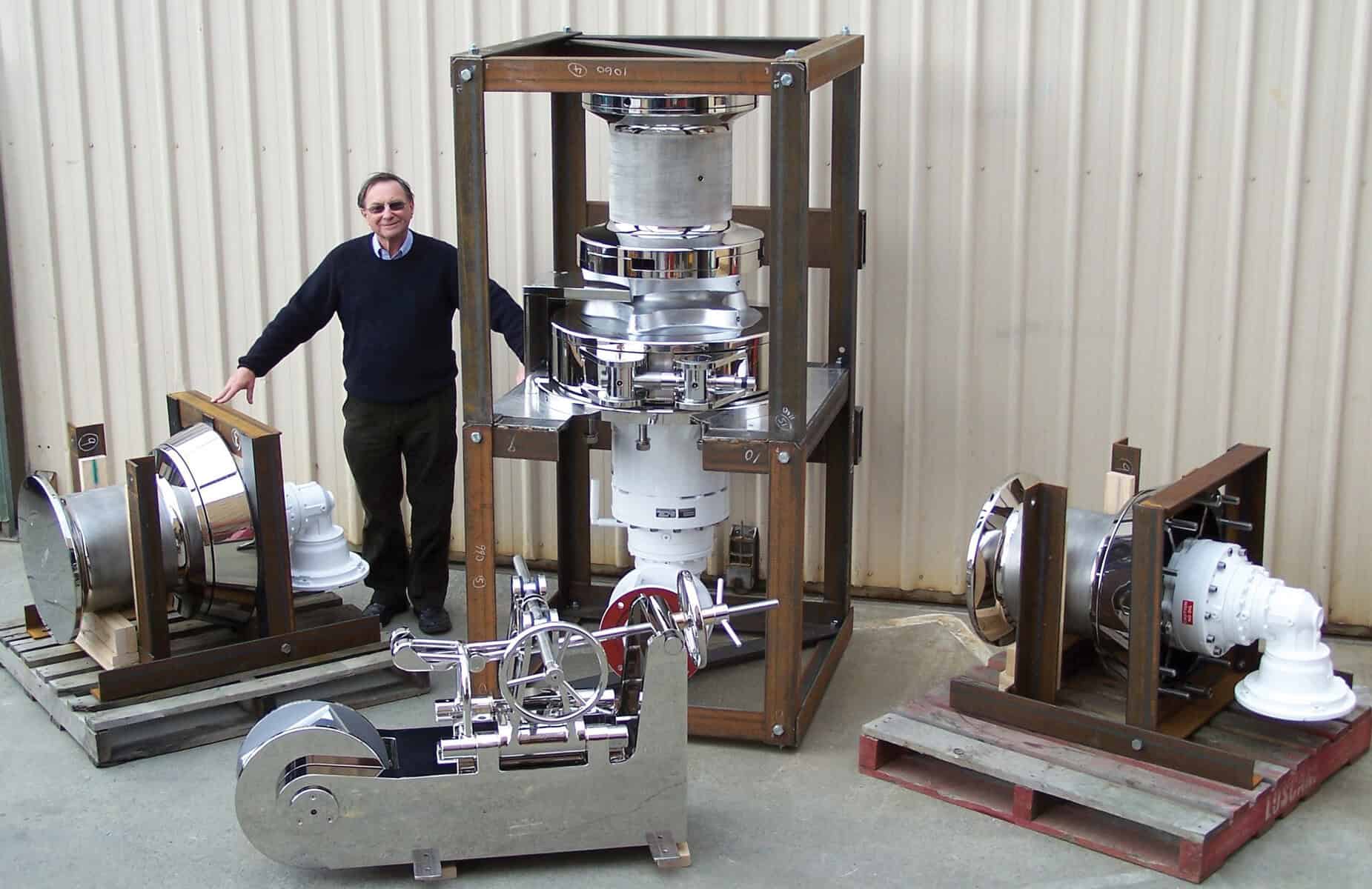
2009:
John with Muir’s largest winch at the time, the VRC24000. Muir can now construct up to a VRC40000.
ANGLED BRAKE HANDWHEEL CALIBRATION
For angled brake handwheel systems to function correctly and ensure effective actuation of the windlass band brake, the handwheel ‘stand’ must be located in the correct position or it can jam the brake handwheel shaft and prevent actuation of the brake band. The following procedure is specific to Muir equipment and may differ with other manufacturers, but it is critical that this is correctly calibrated per your anchoring system supplier instructions..

A. Install winch assembly including brake band (Item 1), brake shaft (Item 3) and thrust collar (Item 2). A thrust washer is also installed on the opposite side of the brake nut to the thrust collar.
B. Temporarily connect the brake handle assembly to the brake band. (Items 4,5,6). Do not install the brake shaft bracket (Item 7).
C. Using the brake shaft assembly, tighten the brake band to its maximum.
D. The handle (Item 6) and brake shaft bracket (Item 7) can now be positioned ensuring that there is exactly “D” mm Gap (the value in the table below) between the universal joint (Item 4) and the shoulder on the brake shaft (Item 3). It is also important to ensure that the brake handle shaft (Item 5) is positioned at the correct angle.
E. Secure all fasteners and test brake release operation.
| Model | D (mm) |
|---|---|
| VRC4500/6000 | 10 |
| VRC8000/11000 | 11 |
| VRC13000/15000 | 13 |
| VRC18000 | 13 |
| VRC20000 | 15 |
| VRC22000 | 18 |
| VRC24000 | 25 |
BASE MOUNTING AND ASSEMBLY
The base shall be the first component of the given piece of equipment (e.g., windlass, stopper, or mooring capstan) to be located in place. Muir suggests an initial test alignment, clearly marking the locations where the requirements for smooth operation, set out earlier in this section, are satisfied.
If the vessel has a curved deck, an appropriately shaped mounting block must be used.
After the alignment is confirmed, the equipment can be welded or bolted in place per the original client specification.
After fitting the base plate in the desired position, the windlass can be reassembled per your anchoring system supplier instruction manual.
SEALING AND ISOLATION
to the extent that excess is observed at the edge of the base plate after tightening of the mounting studs/ bolts.
If the windlass is to be mounted on a steel or alloy deck an insulator, preferably some form of rigid plastic must be used to avoid any problems with dissimilar metals. It is also advisable to insulate the mounting bolts with plastic sleeves. Fasteners should be coated with a dry film lubricant (e.g. Molybdenum disulfide) to reduce direct contact between dissimilar metals, to reduce galvanic corrosion and to reduce the risk from stray currents. Molybdenum disulfide will also prevent galling in situations where two similar metals are used.
All mating surfaces should be thoroughly lubricated with grease suitable for marine applications. As the windlass will be operating in a corrosive environment it is also highly recommended that corrosion protection be used on the external surfaces of the motor and gearbox.
MOTOR SUPPORT BRACKET
If the winch is fitted with a 90-degree gearbox, please ensure that the motor feet are fixed to the deck structure via a motor support bracket. An adjustable packing material, such as a POM plastic, shall be used to perfectly pack the motor, to ensure the gearbox is not stressed when the motor is bolted in place.
Fit the winch and motor before finalising the bracket set up and drilling of the bolt holes. It is critical to avoid stressing the gearbox on 90-degree gearboxes and this must be aligned on site during install.
BOLT TORQUE
It is important that all bolts are tightened to ensure reliability and structural integrity. Unless otherwise stated the following are suggested torque/preload values for the general bolt sizes found on Muir windlasses. Use OEM specific torques for all drivetrain related fasteners.
Thread locking compounds (e.g. Loctite 243) must be used on all critical fasteners to reduce the likeliness of loosening. To reduce seizure / galling and corrosion, use a Molybdenum disulfide lubricant or a product such as NCH Thread-eze ultra to remaining noncritical fasteners.
Bolt tightening torque and pre-load
| Stainless Steel Class 70 | M8 | M10 | M12 | M16 | M20 | M24 |
| Tightening Torque | 16.6 | 35 | 61.2 | 152 | 296.4 | 512.8 |
| Pre-Load(Nm) | 10.8 | 17.2 | 25 | 46.6 | 72.7 | 104.8 |
IMPORTANT NOTE (DISCLAIMER) :
Use of this guide is entirely at your own risk. Your Anchoring System supplier and relevant class society literature must take precedence over this document.
Whilst every care has been taken in the compilation of this information, Muir takes no responsibility for poor Anchoring System performance, or any and all potential consequences that arise from incorrect installation/ layout/ design, directly or indirectly as a result of content provided in this guide.
This is intended as a guide only on the install and layout of Anchoring Systems, and cannot account for all possible variables that may influence the performance of an Anchoring System.
Variation in the requirements of Anchoring System manufacturers must be considered, and the respective documentation and instructions consulted first and foremost.
In particular, an approved and experienced engineer and deck equipment installation agent must be engaged to ensure your equipment is installed safe and proper for use.
Neither we nor our partners, or any of their affiliates, will be liable for any direct, indirect, consequential, special, exemplary or other damages that may result, including but not limited to economic loss, injury, illness or death.
II : EQUIPMENT SPECIFICATION
Anchoring and mooring equipment is selected based on the following inputs:
- Chain Size
- Chain Grade
- Anchor Weight
- Vessel Dimensions and Weight
For vessels subject to a class ruleset, this ruleset will dictate an Equipment Number (EN) based on the vessel dimensions and weight, which then drives the chain size, chain grade and anchor weight.

Chain size (diameter) and chain grade then drive the windlass required pull loads based on a class ruleset defined formula. At Muir, we also check that the windlass meets our own pull requirements, which are often greater than the class requirements.
On U3 (K3) chain, the windlass brake becomes the limiting factor and chain breaking load, rather than chain size, drives the selection of the windlass. There is no clear requirement for mooring capstan sizing from class. At Muir, we use a mixture of our experience, and the equipment number, to select a mooring capstan. Rope diameter may also drive capstan sizing or capstan head height.
III: DESIGN AND LAYOUT
EQUIPMENT LAYOUT
When designing an anchoring system, it is important to consider the following requirements:
- A clear, horizontal chain path.
- Correct positioning and locker sizing.
- Maximizing the wrap of chain around the gypsy.
- Alignment in both horizontal and vertical planes of the equipment.
- Allowing for angular twist and support of the chain.
- Position of the motor and gearbox under deck; and Insulation of dissimilar metals.
CHAIN LOCKER AND SPURLING PIPE
Ideally the chain roller or chain pipe should be positioned centrally over the chain locker. This maximizes fall of chain as it piles up within the locker. The table below provides guidance on minimum fall depth. Fall depth is critical to achieving smooth operation of the windlass as it allows the chain to peel off the gypsy. Increasing the depth assists in “pulling” the chain off the gypsy and reduces the need for “flaking” of the chain into the locker
| Chain Size | Minimum Fall Depth to Top Of Heaped Chain |
|---|---|
| Up to and including 16mm | 800mm |
| From 17.5 to 20mm | 1220mm |
| From 20 to 24mm | 1400mm |
| From 24 To 28MM | 1600mm |
| From 28 To 32MM | 1900mm |
| From 32mm and above | 2500mm or greater |
It is a common mistake to locate the windlass too far forward, or too close to the bulkhead, leaving insufficient room for chain and anchor stowage.
In installations where space is limited a length of ‘lead in’ tube or ‘spurling pipe’ with a bell-end and a bore of at least 1.5 times the chain link length can be used to guide the chain to the center of the chain locker. This extension must be between vertical and 45 degrees off vertical under the deck. Angles more than 450 off vertical will increase chain drag within the tube and impact gypsy performance. Ensure all internal welds are ground down and smoothed out to prevent catching of the chain.
The gearbox can be fitted in multiple positions to allow the chain to fall away from the motor. If the motor is positioned near the falling chain, then a lead in tube or spurling pipe is also recommended to protect the motor.
We recommend calculating the chain height in the locker using a cone height calculation as below. Remember that fall depth is calculated from the top of the heaped chain!
For calculating the volume of stud link chain, you can use the following formula:
V=0.00001095*d2*L
Where
V= Volume of Chain, d= Chain Diameter, L= Length of Chain
You can then calculate the height of the cone using the following formula:
h=12v/D2
Where
V= Volume of Chain, D= Cone base diameter, L= Length of Chain
The base of the cone is conservatively defined as the shortest dimension across the base of the chain locker. This is an estimate only and a 1.2 safety factor should be applied. Complex chain locker geometries will require alternative calculation methods. 3D CAD modelling software can be used to improve estimate accuracy by using the volume calculation above in conjunction with a volume estimate from the software.