


Vol. 2 Commissioning & Operation
Secrets of
Anchoring Systems
Commissioning and operation of yacht and ship anchoring systems.
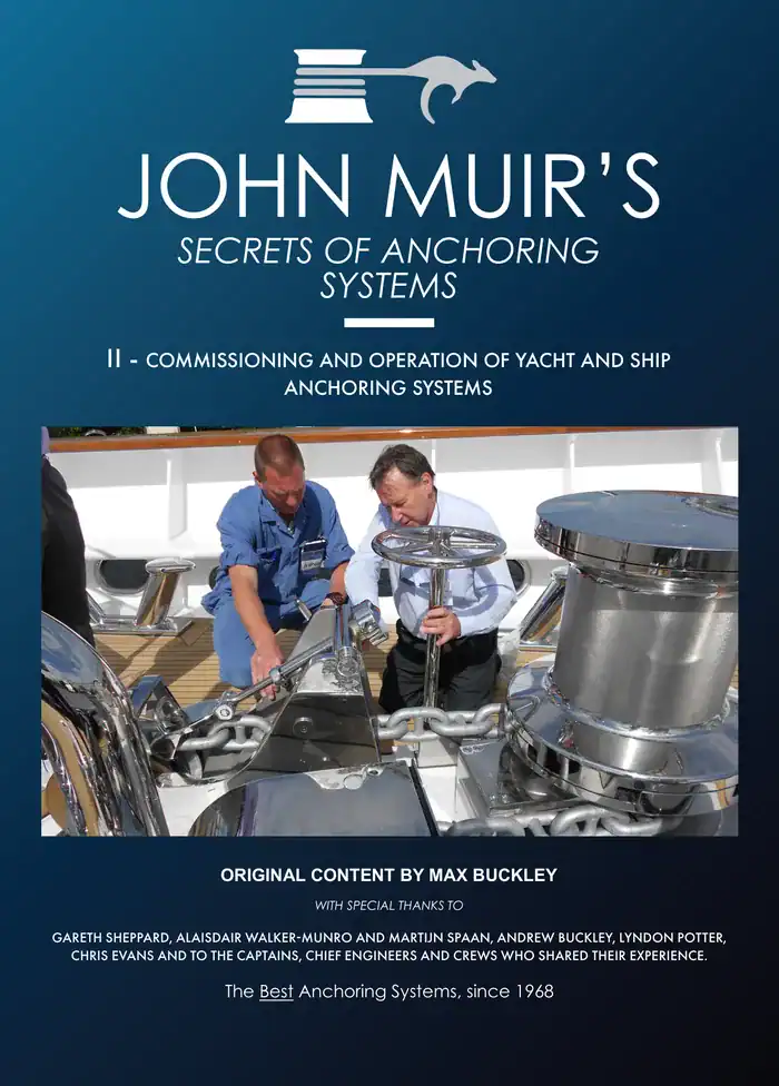
Commissioning and Operation of Yacht and Ship Anchoring Systems
Max Buckley
General Manager
Why this guide?
Most anchoring documentation is written for someone else. The installation manual is written for the shipyard engineer commissioning the equipment from scratch. The recreational guide assumes you have a 50 kg anchor and a 1.5 kW windlass. Neither talks to the captain who has just taken command of a 70-metre vessel, the officer who needs to understand why the brake is applied before the clutch is disengaged, or the chief engineer who wants to know what a properly loaded chain stopper looks and sounds like.
This guide fills that gap. It covers:
- what commissioning involves, and what you, as the vessel’s crew, should expect and verify
- taking command of an unfamiliar system, and what a complete handover pack should contain
- how the system operates in each scenario you will meet: freefall deployment, powered deployment, retrieval, underway stowage and lying at anchor
- the brake in detail: how it works, why smooth application matters, and what the failure modes look like
- correct underway procedure: the compressor, the stopper, the devil’s claw and the brake, in the right order and for the right reasons
- what to do when things go wrong, and how to prepare before they do
- the maintenance fundamentals that keep a system reliable across a full season, including the spares worth carrying.
Read with Volume I (Design, Layout and Installation) and Volume III (Anchoring: A Modern Guide to a Very Old Craft), it gives any crew the full picture, from specification through to safe daily use.
Using this guide aboard. The procedures here are written to be adapted into your vessel’s own Safety Management System under the ISM Code or the applicable yacht code, alongside the equipment manual. Where this guide and the manual differ, the manual governs. Throughout the guide, must marks a safety or warranty requirement, should marks Muir’s recommended practice, and may marks something permitted but not required.
Why it matters. Studies of anchor losses attribute roughly a third to weather, around a quarter to winch or motor failure, and a fifth to operational procedure. Put another way, more than half of all losses trace back to how the equipment was used and maintained, not to the weather. Those are the failures this guide can help you prevent.
The cost of a failure at the bow goes well beyond the repair invoice. As one captain contributing to this edition puts it, it can mean losing a safe anchorage or preferred berth, delaying the guest programme, extra fuel and port costs, crew fatigue and disrupted rest, emergency contractor and freight charges, class, flag or insurance involvement, and damage to the relationship with owner and management. Above all, it increases the risk to the yacht, the people on board, the vessels around her and the environment.
Caution This guide supplements but does not replace your vessel’s equipment manual. Always refer to the manual supplied with your windlass for model-specific procedures, torque settings and service intervals.
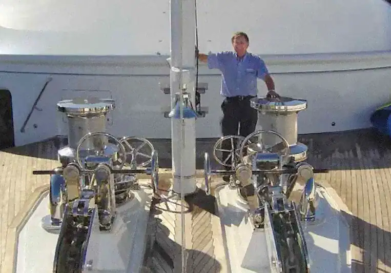
Table of Contents
Contributors to this edition
Volume II draws on the operational experience of three professionals who answered our questions on commissioning, operation, maintenance and what really happens at the bow. Their contributions appear throughout the guide in three kinds of panel: From the Bridge, From the Engine Room and From the Yard.
Our thanks to each of them. Their experience is shared in good faith. Where it differs from the manual supplied with your equipment, the manual comes first.
Alaisdair Walker-Munro
Chief Engineer, MY Sherpa
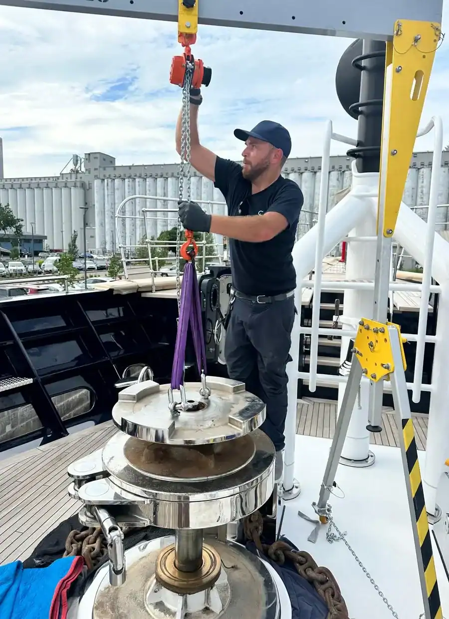
Alaisdair is Chief Engineer of MY Sherpa, a 73.6m Feadship expedition yacht. He joined the superyacht industry in 2010 aboard Mirabella V, and over 16 years has built broad technical experience across both motor and sail yachts. Before that he worked in Class-1 Offshore Powerboat racing, where engineering reliability is pushed to the limit. On Sherpa, he is responsible for maintaining the yacht’s windlasses, including full strip-downs on deck to inspect and service the shaft and bearings. On an expedition yacht that often operates far from shipyard support, that work is essential to safe anchoring.
Gareth Sheppard
Captain, MY Felix
Martijn Spaan
Spaan Marine, Superyacht technical services & Owner’s team support

I: Understanding your system
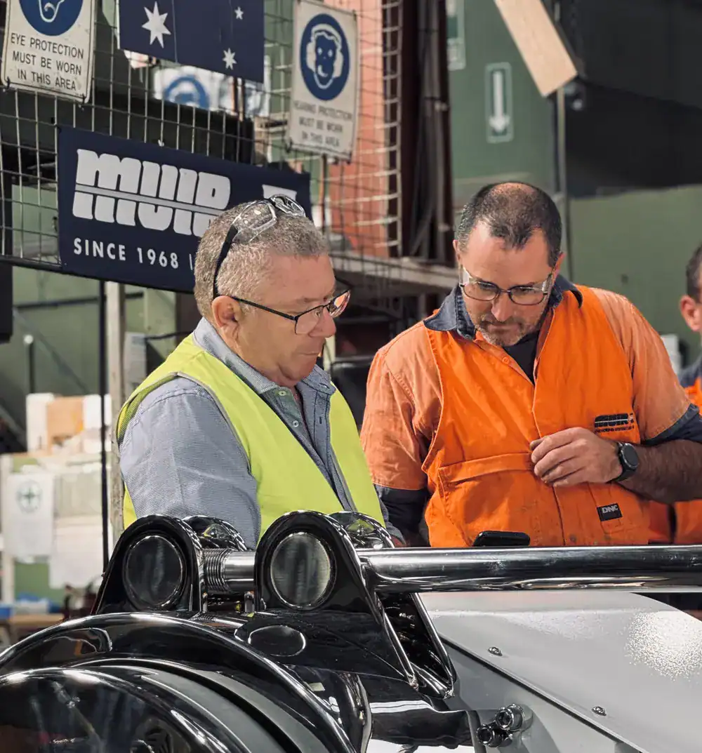
Before you can operate an anchoring system with confidence, you need to know what each component does and how the components relate to one another. The table below covers the key components on a large yacht or ship anchoring system. Volume I gives the design and layout detail behind each of them.
| Component | Role in the system |
|---|---|
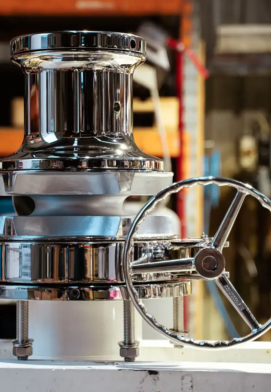
| Windlass | The primary machine that raises and lowers the anchor and chain. On large vessels, typically a vertical or horizontal windlass driven by an electric or hydraulic motor through a planetary gearbox. Contains the gypsy (chainwheel), the band brake and the dog clutch. |
| Gypsy / chainwheel | The toothed wheel on the windlass that engages the chain links to raise and lower the anchor. The chain must have at least 120° of wrap around the gypsy for reliable operation. |
| Band brake | A friction brake mounted on the gypsy drum. When engaged, it holds the chain against gravity and the weight of the ground tackle. The brake is the primary control during freefall deployment, and a critical backup when underway or at anchor. |
| Dog clutch | A mechanical clutch that connects or disconnects the gypsy from the drive shaft. The gypsy must be disengaged (clutch released) for freefall deployment. The clutch must be engaged for powered operation and for the motor brake to work. |
| Chain stopper / compressor | The primary load-bearing device when the vessel is at anchor. It takes the static load of the chain and anchor off the windlass entirely. Designs include high-profile stoppers (with roller, lock and devil’s claw), low-profile stoppers and chain compressors. Designed for static and shock loads; the windlass brake is not. |
| Devil’s claw | A hook or fitting that clamps onto the chain to hold it in position while the stopper is being set, or as part of the stowage arrangement when underway. On many vessels it is one layer of a multi-layered underway stowage procedure. Not designed to take anchoring loads but designed to hold the housed anchor hard into its pocket at sea, which is why it can serve as one of the three underway layers (Section VI). |
| Hawse pipe | The pipe that guides the chain from the deck through the hull to the anchor pocket, where the anchor is stowed when not in use. |
| Chain locker / spurling pipe | The space below deck where the chain is stowed when the anchor is fully heaved. The spurling pipe guides the chain from the deck fitting down into the locker. Correct locker depth is critical to smooth gypsy operation. |
| Mooring capstan | Where fitted, the capstan drums on the windlass tension mooring lines at the fore part of the ship. When the capstan is in use, the gypsy is disengaged to prevent accidental chain movement. Mooring capstans are also often fitted aft on larger vessels to help with berthing. |
These components work as one system, and each has one job. Most operational and mechanical failures begin when a component is asked to do a job it was never designed for. Two cases come up repeatedly: a crew using the windlass brake as the load-bearing device at anchor, when that job belongs to the chain stopper (Section VII); and a vessel putting to sea without all three layers of underway stowage applied (Section VI). Keep each part to its designed role and the system is very strong. Ask one part to cover for another and you spend the safety margin the designers built in.


II: Commissioning
Commissioning is not simply switching the windlass on for the first time. It is a structured verification that the whole anchoring system, from chain locker geometry to torque limiter setting, meets specification before the vessel enters service. On large builds it is carried out by Muir-approved technicians with the shipyard and signed off by the vessel’s master.
As the vessel’s captain or chief officer, you should understand what is being verified, what to expect while it happens, and what documentation you should receive at handover.
What commissioning covers
- Alignment verification: confirming that the windlass, chain stopper, return roller and hawse pipe are correctly aligned in both the horizontal and vertical planes. Misalignment is the most common cause of premature wear, chain jump and noise under load.
- Gypsy wrap: verifying that the chain has a minimum of 120° (preferably 180°) of wrap around the gypsy. Insufficient wrap leads to chain skip and uncontrolled descent.
- Torque limiter setting: the torque limiter protects the drivetrain from overload. It is set during commissioning and must be checked periodically. An incorrectly set torque limiter can cause poor anchor retrieval or equipment damage. A limiter that slips too readily, whether worn or set below specification, shows up as a windlass that struggles to recover chain.
- Motor brake function: on electric drive systems, the motor brake adds a layer of resistance against unintended chain release when the system is powered. The correct air gap is verified during commissioning.
- Brake calibration: on windlasses fitted with an angled brake handwheel, the calibration must be set precisely. Incorrect calibration can make the brake less effective than the operator expects.
- Chain stopper function: confirming that the stopper engages the chain correctly, that the pawls seat fully, and that the stopper can take the full anchor load off the windlass.
- Full operational test: a complete freefall lowering, powered lowering and retrieval cycle with the chain and anchor fitted, confirming smooth operation under representative load.
- Crew training sign-off: all crew training on the equipment must be signed off by the shipyard or the master of the vessel. This forms part of the vessel’s Muir warranty conditions.
Witnessing the tests
A commissioning record proves that each check was carried out. On its own, it cannot prove that the system will perform under realistic load, in real conditions, with your own crew at the controls. The most experienced chief engineers treat the formal test protocol as the minimum, witness every part of it personally, and use the time while the commissioning team is still aboard to find out how the system behaves when it is pushed.
Commissioning paperwork does not necessarily prove the complete system works properly under realistic load.
Gareth Sheppard, Captain, MY Felix
From the Engine Room
At commissioning I witness the complete harbour acceptance test protocol, carry out my own visual inspection and personally verify every check. On our most recent upgrade, the classification society’s test requirements and the supplier’s differed, so we elected to test to the limit of operation: lowering nine shackles one at a time, turning around at each shackle to prove we could recover, before reaching nine shackles hanging free in deep water and recovering at high speed all the way.
I won’t operate any equipment after service until the contractor lead tells me to; it’s better to have the manufacturer break it before it’s handed over. Once the acceptance tests are complete, I like to drive it myself in a more realistic and less friendly way than I’ve just watched, including abrupt direction changes. Better to find a fault in a torque limiter or motor setting while the manufacturer is present than later down the track.
Alaisdair Walker-Munro, Chief Engineer, MY Sherpa
Caution Demanding tests of this kind, including abrupt changes of direction, belong only in commissioning and only under the direction of the commissioning technician. Never use them in routine operation. On DOL electric drives in particular, see the caution in Section V.
What you should receive at handover
At handover, the vessel’s master must receive a completed Muir Commissioning Form, signed by the commissioning technician. It records the key measurements, settings and test results from commissioning and gives a baseline for future service intervals.
The form is the core of the handover record, but not all of it. Experienced captains expect a complete anchoring system handover pack, including:
- anchor, chain, joining shackle and swivel specifications
- chain certificates, inspection history and measured wear
- windlass manuals, drawings and electrical or hydraulic schematics
- brake holding-load calculations, test results and the manufacturer’s brake-setting procedure
- safe working loads and system limitations
- chain counter calibration records, where a counter is fitted
- the bitter-end arrangement and its emergency release procedure
- planned maintenance history, outstanding defects and the critical spares inventory
- photographs of key components and of correct chain orientation
- normal, emergency and equipment-failure procedures
- records of actual anchoring performance in different seabeds and conditions
- a backup of the windlass control system configuration (e.g. VFD parameters), together with all access passwords.
From the Bridge
What is often missing is the practical, vessel-specific information: how the brakes actually feel, how much chain remains before the bitter end, whether the chain counter is genuinely accurate, known operating quirks and what has previously failed under load.
Gareth Sheppard, Captain, MY Felix
From the Engine Room
One thing I have learnt over the years is to ask for a backup of the PLC/VFD configuration, along with all the passwords, to be handed over at final sign-off.
Alaisdair Walker-Munro, Chief Engineer, MY Sherpa
If your vessel has had a refit, a chain replacement or any work affecting the anchoring system, have commissioning re-verified before she returns to service. Do not assume that a system that worked last season will work correctly after major deck work. When you re-verify, check the whole load path, not just the new part: a new component is no guarantee that the joining arrangement, swivel orientation or adjacent components have been assembled correctly.
Caution Anchoring and mooring operations, including crew training, must not be carried out until all equipment has been commissioned by the shipyard or a Muir-approved technician. The vessel must not leave port without a completed and signed commissioning record.
Taking command of an unfamiliar system
A captain taking command of a new vessel inherits an anchoring system with a history they did not write. Before anchoring her for the first time, it pays to understand both the equipment and how the vessel behaves on it.
- Inspect the equipment: the anchors, chain condition and certification, the bitter-end arrangement, windlasses, brakes, clutches, chain counters, any hydraulic systems, the controls and the emergency recovery options.
- Review the records: previous defects, maintenance records and any recent yard work.
- Talk to the people who know her: the outgoing captain, chief officer, bosun and chief engineer, separately. Each will hold different operational knowledge.
- Know her limits before you need them: before entering a crowded bay or difficult conditions, establish the vessel’s windage, turning behaviour, expected swinging circle and holding limits, and how quickly you can abort or recover if something goes wrong.
From the Bridge
A manual can explain the correct settings and operating sequence, but it cannot tell you whether the brake engages progressively, whether the chain jumps or piles incorrectly in the locker, whether the counter is accurate after several shackles, or how the hydraulic system responds when both windlasses are operating.
Gareth Sheppard, Captain, MY Felix


III: Operating the system
The procedures below apply to Muir vertical windlass systems with a positive-lock dog clutch, and assume the equipment has been correctly commissioned. Refer to your vessel’s equipment manual for any model-specific variation.
From the Yard
On the larger yachts we work on, the variable frequency drive starts the motor up nice and slowly to minimise the impact on the motor and the power surge; the slope of the ramp-up is beautiful. I’ve tested operation from a guest and owner’s cabin: you can hear it and feel it, but it isn’t disturbing, and we’ve had no negative feedback from guests.
Martijn Spaan, Spaan Marine
Before you start
Know the limits. Every windlass has a rated continuous pull, a short-term overload pull and a rated speed. They are on the nameplate and in the handover pack (Section II). Brief the crew on them. Section V explains how to read the load by ear, but the numbers are the reference.
Agree who has control. Many larger yachts can operate the windlass from the bridge or a remote station as well as locally, often with cameras and a chain counter. Before any anchoring operation, confirm which station has control, where the emergency stops are, and that the foredeck can stop the operation at any time.
Standard reports. Agree the calls between bridge and foredeck before the first operation and use them every time: how the chain is leading (ahead, abeam, astern, up and down), the stay (long or short), “anchor aweigh” and “brought up”. A call nobody recognises, or a mark nobody can read at night, is how too much chain gets let go.
Personal safety. Nobody stands in the bight of the chain or in line with it under load. Eye and hearing protection for freefall, gloves for chain handling, and nothing loose near the gypsy or capstan. A one-minute toolbox talk before each operation is cheap insurance.
Dog clutch operation
The dog clutch connects the drive shaft to the gypsy, so the motor can power the chain up or down. When the clutch is disengaged, the gypsy runs free on the shaft, allowing freefall deployment with the brake as the only control.
Correct engagement is critical. If the drive dogs are not properly aligned before the clutch nut is tightened, the dogs will be damaged: an expensive repair, and an entirely preventable one.
To engage the clutch correctly:
- With the capstan head raised clear of the drive dogs, inch the windlass slowly using the controls, or use the brake band to slowly lower the chain, until the dog clutch alignment indicators line up.
- Engage the drive by turning the clutch nut clockwise until the capstan (or low-profile clutch) is fully lowered onto the gypsy.
- Back the clutch nut off half a turn anticlockwise.
- Slacken the brake slightly to let the gypsy rotate. This fully seats the dog faces for anchor retrieval.
Caution Do not overtighten the clutch nut on a dog-driven windlass. The capstan head should move freely up and down on the drive shaft. If it does not, re-inspect the dogs and make sure they are not contacting each other.
Lowering the anchor
There are two ways to lower the anchor, and they share the same preparation and the same finish. Powered lowering is the preferred method, particularly in shallow water or confined anchorages where precise depth control is needed; the drive motor controls the rate of descent. Freefall is the fastest way to get the anchor down and is used in most time-critical situations; the weight of the chain and anchor pulls the ground tackle down, and you control the rate with the band brake alone. Freefall is where operating skill and brake technique matter most, so read Section IV before your first one.
Preparation (both methods)
- Engage the clutch following the dog clutch procedure above.
- If the devil’s claw is engaged, release it.
- Loosen the brake band by turning the brake handle anticlockwise.
- Release the load on the chain stopper by briefly powering the windlass in the up direction. (If there is no power, use the devil’s claw to pull the chain in slightly to achieve this.)
- Disengage the stopper pawl(s).
Powered lowering
- Use the hand or foot control to lower the anchor at the required rate.
Freefall lowering
- Apply the brake before attempting to disengage the clutch.
- Disengage the gypsy by rotating the clutch assembly anticlockwise until the dog clutch is fully clear of the dogs.
- Lower the chain and anchor by slowly releasing the brake, using it to control the rate of descent throughout.
Setting and securing (both methods)
- Once the anchor is at the required depth, engage the brake band and set the anchor using the vessel’s engines. See Section VII for how to tell when the anchor is set.
- After a freefall, re-engage the clutch following the dog clutch procedure above, so the windlass can be used to position the chain for the stopper.
- Engage the chain stopper to take the load off the windlass (Section VII).
- Tighten the brake band fully as a secondary backup, and leave the clutch engaged while at anchor so the motor brake adds a third barrier, as it does underway.
Tip Where time and depth allow, walk the anchor back under power rather than letting it freefall. Lowering under power gives you positive control of the rate, lays the chain out along the seabed rather than in a heap, reduces the twist a fast, uncontrolled drop puts into the chain, and saves wear on the brake lining. A long freefall also puts a lot of heat into the lining; see Section IV.
Warning Apply the brake smoothly and progressively, exactly as you would a vehicle brake. Snatching the brake on and off causes chain whip, which generates very large forces and creates a serious injury risk for anyone near the windlass.
Warning Never lie at anchor on the windlass brake alone. Transfer the load to the chain stopper as soon as the anchor is set (Section VII). The stopper is designed for static and shock loads; the brake is not, and relying on it alone at anchor risks catastrophic failure.
Warning Never drop the chain stopper pawl into the stop position while the chain is running out. The sudden shock load can be catastrophic.

IV: The brake: understanding smooth operation
Of everything involved in operating an anchoring system, the brake asks the most of the operator and is the least forgiving of mistakes. Read this section carefully, even if you have run anchors for years. The difference between a well-managed operation and a dangerous one is almost entirely a matter of feel, and feel is the one thing a manual cannot give you.
It’s this finesse, combined with procedural discipline, that really enhances safety.
Max Buckley, General Manager, Muir Anchoring Systems
What the brake does
The band brake is a lined steel band clamped around the gypsy drum. Turn the handwheel clockwise and the band tightens, resisting the drum’s rotation through friction alone. When the gypsy is declutched and the anchor is running out in freefall, that friction is the only thing between a controlled descent and a runaway. There is no motor, gearbox or electronics in the load path, only your hand on the wheel.
The holding figures are large: on a 32 mm stud-link system the brake is designed to hold around 40 tonnes. But holding capacity and control are two different things, and it is control that keeps people safe. A brake can be more than strong enough to stop a chain and still be operated in a way that injures someone. What decides the outcome is not how hard the band can grip, but how smoothly you apply that grip.
Applying the brake
Think of it as you would the brakes on a car. No one goes from fully off to fully on in an instant at speed; you feed the pressure in progressively and feel the result through your hands. The windlass brake needs the same touch. Snatch it and the chain whips violently. Squeeze it on progressively and the chain comes to rest where you planned.
During a controlled freefall, your job is to:
- start with the brake lightly applied, so the chain runs at a steady, controlled rate
- progressively increase brake pressure as the anchor approaches the target depth, slowing the descent smoothly rather than stopping it suddenly
- never fully release the brake and then snap it back on. This is the most common cause of chain whip, and a cause of incidents documented in maritime safety reports
- keep one hand on the brake handwheel at all times during freefall. The chain is not under your control unless your hand is on the brake.
A good operator running a large anchor out in calm water makes it look easy. The chain runs cleanly through the gypsy without jumping, the rate is steady and unhurried, and the stop is a gradual settling rather than a bang. It nearly always takes longer than a newcomer expects. That unhurried pace is not caution for its own sake: it is what keeps the load, and the people around it, under control.
Tip In deep water, walk it back; don’t let go. Letting go with several shackles to run means a long run on the brake, a hot lining by the time the anchor is on the bottom, and a runaway that is harder to arrest the deeper it gets. Walking back in gear keeps the chain under control from the hawse pipe to the seabed, lays it out along the bottom instead of in a pile, and lets the bridge bring her up on a known scope. Keep freefall for shallow water and for the occasions when speed matters more than finesse.
Tip Make sure the brake band gaps specified on the Muir drawings have been set correctly at installation.
Tip Muir partner TBS Marine in Italy has published a practical video showing smooth brake handling on a Muir VRC15000: Windlass Braking Systems. If your crew has not seen it, watch it before your first operational deployment.
Warning If control is lost during freefall and cannot easily be regained with the band brake, clear the area around the windlass immediately. Do not attempt to stop the chain by any other means. The energy in a runaway chain is extremely high.
Muir’s brake design philosophy
Muir’s larger brakes are built on a principle we call inherently safe design: the critical mechanical elements, the actuation system and the band retainer, each have independent redundancy, so that a single failure in either should not take control away from the operator. Two other failure modes, lining wear and heat fade, are not something redundancy can solve; they are prevented by maintenance (Section XI) and by technique. It is easiest to understand all four by first looking at the ways a conventional brake can fail.
Four failure modes dominate conventional brake designs:
- Failure of the actuation system: the mechanism that clamps the brake band to the drum. If this fails, the operator loses brake control entirely.
- Failure of the brake band retainer: the lug or block that transfers torsional load from the band to the windlass base. If this fails, the brake band can rotate with the drum rather than resisting it.
- Failure of the wear interface: brake lining worn beyond the safe operating limit. Easily prevented with the correct maintenance schedule; easily missed when maintenance is deferred.
- Heat build-up in the lining: a long or repeated freefall turns the energy of the descending chain into heat at the brake lining. As the lining heats, its grip falls away, so a brake that held firmly at the start of a deployment can fade towards the end of it. Prevented by technique: walk the anchor back under power wherever time and depth allow and avoid repeated long freefalls in quick succession.
From the Engine Room
I have witnessed a runaway in freefall caused by an overheating brake band. Luckily the windlass was mounted below deck in a sunken compartment, so the whipping end of the chain only smashed up some deck fittings on its express trip out of the hawse pipe.
Alaisdair Walker-Munro, Chief Engineer, MY Sherpa
On an open foredeck, with crew standing at the windlass, the outcome could have been very different.
Muir’s design response to the first two failure modes includes:
- A captive handwheel held securely against a machined shoulder on the brake shaft. Even if the securing bolt and washer are lost, the handwheel keeps working because of the machined shoulder. Drive is transmitted through a captive key.
- Bronze brake nuts with three levels of redundancy, held captive in welded brake nut lugs and secured with self-aligning washers or stainless-steel circlips. Bronze is used specifically to prevent binding on the stainless-steel shaft, giving smooth actuation in all conditions.
- A brake band retainer welded permanently to the band and designed to float within the peeler upright or windlass base block. This floating design lets the brake band self-align with the drum, giving even pressure and preventing stress concentrations.
For you as the operator, the practical result is simple: a properly maintained Muir brake behaves the same way every time you use it. That consistency is the point of the engineering. The brake you learned on, on the first calm morning of the season, should feel the same under your hand when you have to let go in a hurry on a dark night at the end of it. It is designed to.


V: Raising the anchor
Retrieval is the reverse of deployment, but it carries its own risks. The most common mistake is using the windlass to drag the vessel up to the anchor, rather than motoring up to the anchor and then winching. Dragging the vessel puts very high loads on the windlass, loads it is not designed to carry, and can cause significant equipment damage. The same rule applies on a 10-metre cruiser and a 100-metre yacht: drive the boat to the anchor, then lift.
Chain marking
Before your first deployment of the season, or in any new anchorage, confirm that your chain is correctly marked. Muir recommends painting three individual chain links in a bright, contrasting colour:
- one to show when the anchor breaks the water surface
- one to show when the anchor is within 1500 mm of its stowed position
- one to show when the anchor is within two links of its stowed position.
These three marks are in addition to the shackle marks carried on every large vessel: paint and seizing wire on the links either side of each joining shackle, counting outward from the anchor, so the crew can see how many shackles (27.5 m each) are out. Repaint them at every docking and check them after any chain work.
These marks let the operator and foredeck crew communicate clearly and safely during retrieval, without hand signals or shouting across a noisy deck.
Chain counters, where fitted, are a useful aid, but their accuracy can drift over several shackles, and a counter is only as good as its last calibration. Treat the painted marks as the reference and check the counter against them.
Retrieval procedure
- Use the vessel’s engines to take the weight off the chain and keep it leading ahead, working the vessel up towards the anchor as you heave. The windlass must only lift the weight of chain and anchor, never pull the vessel. The foredeck reports lead and stay to the bridge throughout.
- Engage the drive clutch by rotating the clutch nut clockwise, following the dog clutch procedure in Section III.
- Release the brake band.
- Release the chain stopper. The windlass may need to be powered briefly in the up direction to take the load off the stopper.
- Operate the windlass to lift the anchor and chain.
- When the first mark appears, slow the retrieval rate. The anchor is now breaking the water, and this is when fouled anchors and tangled chain become apparent.
- At the second mark, inch the windlass carefully. Make sure the anchor is correctly aligned with the hawse pipe and anchor pocket.
- At the third mark, stop. Best practice is to use the devil’s claw to pull the anchor the final distance home into the pocket. If using the windlass to bring the anchor fully home, use very slow speeds.
Listen to the windlass
The electrical cutout is a last line of protection, not a working limit. Crews who routinely haul until the windlass trips are slipping and wearing the torque limiter on every cycle, until it needs adjustment. That costs their engineers hours of work that good technique would have saved.
A good operator reads the strain through the sound of the machine, stays aware of how the vessel is moving in the conditions, and watches the angle of the chain relative to the depth. The same lead angle in 30 metres of water means a far greater hauling load than in 10 metres. If the windlass is labouring, the answer is almost always to use the engines to bring the vessel up to the anchor, not to ask more of the machine.
Caution On systems with DOL (direct on-line) electric drives, the motor reaches full speed quickly when the direction is reversed. Inch the control carefully when the anchor comes out of the water.
From the Engine Room
If I could change one habit, it would be operating the windlass up to the point of electrical cutout, rather than listening to how the strain sounds through the equipment. Train the crew to recognise that sound, to be aware of how the boat is moving in the prevailing elements, and to operate the windlass accordingly.
Alaisdair Walker-Munro, Chief Engineer, MY Sherpa


VI: Correct procedure when underway
Three fail-safes protect the system when underway. All three must be applied: not two, not one. All three.
Muir Anchoring Systems
If you read only one section of this guide, read this one. An anchor and several tonnes of chain released while the vessel is making 15 knots in a seaway is a serious hazard: to the hull, propeller and rudder, to any crew on the foredeck, and to whatever the ground tackle hits when it reaches the bottom. Class rules assume the anchoring gear will be properly secured for sea. They do not assume it will hold a vessel under way, and neither should you.
Muir’s design gives you three independent barriers against an unintended release at sea, and they are meant to be used together. Each is capable on its own, but each can also fail without anyone noticing: a stopper pawl that was never fully seated, a brake that is only snug, a clutch not fully engaged. The reason for three layers is that no single unnoticed failure should ever be enough. Applying two of the three leaves you one barrier short. Apply all three, every time.
The three layers of underway security
Layer 1: chain stopper or devil’s claw
The chain stopper or devil’s claw must be engaged on the chain. Where the vessel’s configuration allows, both may be engaged at the same time, but this is not a requirement; the normal design intent is to use one or the other. This is not a contradiction of Section VII. The devil’s claw is not an anchoring device, but holding the housed anchor hard into its pocket is exactly what it is designed for, and that is the job it does at sea.
This layer holds the chain mechanically at deck level, so the full load of the anchor, chain and any dynamic forces (wave action, vessel pitching) go directly into the vessel’s structure, not the windlass.
Layer 2: the band brake
The windlass band brake must be fully engaged on the gypsy brake drum. That means the handwheel fully tightened clockwise, not just snug or partly applied.
Underway, the brake is not the primary load-bearing device; that role belongs to the stopper or devil’s claw. The brake is the secondary restraint. If the stopper fails or the chain jumps free of the devil’s claw, the brake is what prevents an immediate uncontrolled descent. An operator who leaves the brake only partly applied has removed one of the three layers of protection without knowing it.
Layer 3: the dog clutch
The dog clutch must be engaged when the vessel is underway, with the capstan or dog plate fully lowered. This means the motor brake of the AC or hydraulic drive motor is providing additional restraint on the gypsy. When the clutch is disengaged (as it is during freefall deployment), the motor brake is bypassed. With the clutch engaged, the motor’s internal braking adds a third physical barrier against any unintended chain movement.
The correct underway sequence
Once the anchor is fully heaved and stowed in its pocket:
- Engage the chain stopper or devil’s claw on the chain.
- Fully tighten the windlass band brake handwheel (clockwise).
- Make sure the dog clutch is engaged (capstan or dog plate fully lowered onto the gypsy).
- Confirm the anchor is seated correctly in its pocket and the chain is led cleanly through the hawse pipe.
- Secure any deck covers or chain pipe covers in line with your vessel’s standard operating procedure.
Warning Failure to follow the correct underway stowage procedure can result in the anchor and chain releasing while the vessel is making way. Consequences include severe damage to the hull, propeller and rudder, and potentially injury or death to those on board or in the water.


VII: Correct procedure when at anchor
Getting the anchor to bite is only the first step. Anchoring well means confirming the anchor is holding, transferring the load from the windlass to the stopper, and backing it up with the brake, in that order. The stopper is designed for the static and shock loads of a vessel at anchor; the windlass brake is not, and the windlass itself was never meant to carry them.
Make sure the anchor is set first. As the chain is paid out and the vessel loses way, watch how the chain behaves. If it tightens steadily, comes taut and then eases back into a slack curve, the anchor is holding. If it stays bar-tight and snatches, or keeps running out without settling, the anchor is not holding: pay out more chain or start again.
Setting the chain stopper
- Once the anchor is set and the correct scope is out, use the windlass to position the chain so the stopper pawl(s) can be engaged cleanly.
- Engage the stopper pawl(s). On a Muir low-profile or high-profile stopper, the pawl rotates into position with a simple lever arm. On a compressor design, spin the compressor handwheel clockwise to bring the compressor arms together and the pawls down onto the chain links.
- With the stopper engaged, power the windlass gently outward (pay out) until the stopper takes the full load of the chain and anchor. You will see and feel the load transfer.
- Re-engage the band brake as a backup.
The practical test of a correctly loaded stopper is simple: the chain should be taut between the anchor and the stopper, and slack between the stopper and the windlass gypsy. If there is tension on the windlass side of the stopper, the load transfer is incomplete.
A correctly running stopper also sounds right. The chain should pass straight through without deflection or twist, and the links should lie smoothly on the roller without sagging. The roller itself should be greased and turning freely. The only noise should be the clunk of each link seating into the roller; any other sound, or visible wear between the roller and its shaft, should be investigated.
From the Engine Room
The easiest way to teach someone what an improperly loaded stopper looks like is to wait until the chain has a twist, then operate it slowly and for a short period, so they can hear and see the difference in how the chain flows through the roller and onto or off the gypsy. I do the same with greasing, pointing out the normal level of grease before and after, so they have a visual reference for what right looks like.
Alaisdair Walker-Munro, Chief Engineer, MY Sherpa
Warning Never use the devil’s claw as a chain stopping device at anchor. It is not designed for these loads and using it this way risks failure of the claw, the chain attachment point, or both.
Scope: how much chain to pay out
Scope is one of the most important factors in holding performance, and it is worth knowing the design basis. Class rules size anchoring equipment on the assumption that the vessel is in good holding ground, in sheltered water, with a scope of between 6:1 and 10:1 (chain paid out to water depth), in a current of up to 2.5 m/s and a wind of up to 25 m/s, with no waves. For large yachts and ships with all-chain rodes lying in calm, sheltered conditions, Muir recommends a minimum scope of 4:1. Increase it to 6:1 or more as the wind gets up, the holding is doubtful or the anchorage is open, and you are then within the class basis. Total depth is measured from the hawse pipe or bow roller height above the waterline to the seabed at high water. Crews on large vessels usually count in shackles: one shackle is 27.5 m (15 fathoms).
If in doubt, let it out.
The weight of chain in the water (the catenary) is itself a shock absorber. More chain means more catenary, which means lower peak loads on the anchor and holding system when the vessel pitches or surges. Shortening scope to save chain never pays in heavy conditions.
Tip In any anchorage with swell, gusts or wind against tide, rig a snubber, or better, a two-legged bridle, to take the working load off the chain and stopper. The stretch in the nylon absorbs the shock loads that rigid chain transmits. A well-set snubber can cut peak loads substantially, and a bridle also steadies a bow that is yawing at anchor. It puts the load onto your mooring points rather than the windlass, which is exactly where it belongs.
Anchor watch
Keep an anchor watch as your vessel’s standing orders require: on larger yachts, the officer of the watch using radar ranges, visual bearings and the anchor-watch function on the ECDIS or plotter; on smaller vessels, a drag alarm set from the drop point. Tighten the watch whenever conditions are deteriorating, holding is uncertain or the anchorage is congested. A drag alarm does not replace a person on watch in serious conditions, but it will raise the alarm before a developing situation becomes a crisis.
If the vessel does drag, pay out more chain as your first response: it is quick, often enough, and costs nothing. If she keeps dragging, have the engines on standby, be ready to heave up, and re-anchor in a better position rather than persisting with an anchor that has clearly not found holding. Never try to hold a dragging anchor by powering ahead against it. That loads the whole system dynamically, in exactly the way class rules warn it was never built to withstand.

VIII: Chain twist
Chain twist builds up gradually and often goes unnoticed until it causes a visible problem. Left uncorrected, it will eventually cause chain jump on the gypsy, erratic deployment and retrieval, and accelerated wear on every component in the chain path. Volume I sets out how much twist the chain can accommodate between components at the design stage; this section is about keeping it out in service.
Preventing chain twist
- Controlled braking during freefall greatly reduces chain jumping, the main cause of twist. Fast, uncontrolled descents let the chain bounce and rotate freely as it falls through the hawse pipe.
- When new chain is installed, make sure there is no twist between the stopper, windlass, return roller and bitter end before the first retrieval.
- Fit a swivel between the anchor and chain. This lets the anchor rotate freely without winding rotation into the chain.
- During retrieval, particularly after a long deployment, stop the windlass periodically while the anchor is still below the bow, so the chain can hang freely and untwist before final stowage.
Removing chain twist
Work back from the anchor. The principle is to isolate the section of chain that contains the twist and let it unwind in a controlled way.
- Twist between the anchor and chain stopper: make sure a swivel is fitted, then let the anchor out until its swing path is clear of the vessel and allow the chain to untwist freely.
- Twist between the chain stopper (or return roller) and the windlass: engage the devil’s claw and stopper, release tension on the chain by powering the windlass down, isolate the windlass, remove the chain from the gypsy, untwist the chain and reassemble.
- Persistent twist from the chain locker: carefully let all the chain out until a manageable length remains. Engage the stopper, devil’s claw and band brake, isolate the windlass, remove the bitter end and untwist the remaining chain.
Warning Take great care when handling chain to remove twist. Make sure stoppers and devil’s claws are engaged to prevent uncontrolled release. Use ropes and tools rather than bare hands where possible and always isolate the windlass electrical supply before working on the chain path.

IX: When things go wrong
Every procedure in this guide is designed to keep the system out of trouble. This section covers what to do when it gets into trouble anyway: a brake that will not hold, a windlass that stops with chain out, a stopper that will not engage when it matters. Decide how you would respond before it happens, not at the bow at 0300.
First priorities
When anything abnormal happens during an anchoring procedure (an unfamiliar noise, a jump, a brake that feels wrong, a windlass that stops), work through the same four priorities, in order:
- Stop the deployment. Do not try to push through an abnormal noise, movement or reading in the hope that it clears.
- Keep control of the vessel. The vessel, not the windlass, is the priority. Use propulsion and helm to keep her safe while the problem is assessed.
- Communicate clearly between the bridge, foredeck and engine room, so everyone involved has the same picture of what has happened and what happens next.
- Decide on the safest option: recover the anchor, deploy the second anchor, hold position using propulsion, or abort altogether.
Runaway chain in freefall
If control is lost during freefall and cannot easily be regained with the band brake, clear everyone from the area around the windlass immediately and do not attempt to stop the chain by any other means (see the warning in Section IV). A runaway is more likely late in a long freefall, when the lining is hot. Once the chain is running, the bitter-end arrangement is the last line of defence. That is why it belongs in every handover pack, and why every member of the deck crew must know where it is.
Loss of power
In a power-loss situation, the load can still be taken off the chain stopper by using the devil’s claw to pull the chain in slightly (see Lowering the anchor, Section III). Know your vessel’s emergency recovery options, and test them, before you need them.
System failure with chain out
From the Engine Room
What keeps me awake at night? Having a system failure with all the chain out.
Alaisdair Walker-Munro, Chief Engineer, MY Sherpa
A windlass that fails with all or most of the chain out leaves the vessel attached to the seabed with no quick way of recovering it. The master and chief engineer should agree in advance what the options are for their vessel: recovering by alternative means, riding to the anchor while repairs are made, or buoying and slipping the chain at the bitter end. Buoying and slipping (attaching a float to the end of the chain and recovering the chain and anchor later) may be the only option. Make sure the equipment and crew knowledge for each option are in place.
Rehearse it
Test critical systems before you need them. Walking the crew through the emergency procedures alongside, in calm water and good light, takes an hour. Discovering at night, in a rising wind, that no one knows where the bitter-end release is costs far more.
X: Mooring capstan operation
Where a mooring capstan is fitted as part of the windlass assembly, it tensions mooring lines at the fore part of the ship. The capstan and windlass share the same drive shaft, so only one can be in primary use at a time.
- Before operating the capstan, make sure the gypsy clutch is disengaged and the windlass brake is fully engaged. This stops the gypsy rotating while the capstan is under load.
- Put at least three wraps of mooring line on the capstan head. Fewer wraps risk slipping under load.
- The line angle up to the capstan must be at least 100 degrees to give enough friction.
- Make sure hands and clothing are clear of the capstan before starting it.
- Start the capstan in the retrieve direction. On two-speed capstans, use high speed to take in slack line, then switch to low speed when the line comes under tension.
- As the mooring line becomes taut and the line diameter compresses, stop the capstan. The load must then be taken on the mooring bollard.
Caution Never leave the vessel moored on the capstan unless the system has been specifically designed for it. The capstan is a tensioning device, not a cleat. The load must be transferred to a designated mooring point.

XI: Maintenance overview
This section gives crew an operational overview of maintenance priorities. Detailed service procedures are in the vessel’s equipment manual and must be carried out by Muir-approved service technicians at the intervals in the maintenance schedule.
After every use
- Rinse the above-deck components with fresh water to remove salt and other contaminants. Salt build-up accelerates corrosion of brake band hardware, drive shaft keys and base-plate fastenings.
- Inspect the chain for twist, deformation or unusual wear after each deployment.
- Inspect the chain stopper pawls for visible damage or deformation after heavy anchor use.
- Stow control pendants with care and refit the covers on pendant plugs whenever a pendant is disconnected. Exposed terminals corrode quickly in salt air, and pendants handled roughly have a short working life.
Regular checks (every 2 to 3 months)
- Grease all nipple points: clutch nut thread, capstan head, gypsy, brake band lugs and base plate bearing.
- Check the gearbox oil level through the level indicator window.
- Inspect the brake band lining. On VRC8000 to VRC26000 models, replace the lining when any securing screw head is within 0.5 mm of the lining contact surface. On smaller models, replace it when lining thickness is below 2 mm at any point.
- Check all deck bolt fastenings and drivetrain bolts for tightness.
Watching for gradual change
Some of the most valuable maintenance is simply watching. Wear often develops so gradually that the crew who operate the system every day stop noticing it. Whenever possible, an engineer should watch anchoring operations specifically to listen and look for changes in noise or behaviour that the operators may have grown used to.
From the Engine Room
A season in practice: the routine aboard one heavily used superyacht, run alongside the manufacturer’s schedule.
Daily: visual inspection; check the chain stopper is loaded correctly; check the grease on the roller, guillotine screw and devil’s claw screw; check below-deck equipment for signs of leaks.
Weekly: check the gearbox oil level.
Monthly: inspect the electrical cabinet, check the cooling fans and clean the cabinet filters.
Every two months: grease all above- and below-deck grease points.
Every two years, due to our usage: strip down all above-deck equipment, remove all the old grease, inspect thoroughly and clean out accumulated debris, reassemble with fresh assembly grease, torque all fasteners to specification and change the gearbox oil.
Alaisdair Walker-Munro, Chief Engineer, MY Sherpa
Annual service
Annual service must be carried out by a Muir-approved technician and includes a gearbox oil change, torque limiter inspection and adjustment, motor brake inspection and adjustment, full brake system inspection, shaft and bush wear assessment, corrosion inspection and paint touch-up, and an earth leakage test. A five-yearly service adds replacement of the brake lining regardless of measured wear, and a full inspection of all welds on the chain stopper.
Chain, class and the survey cycle
The chain is a class item, and it is the one component the windlass crew tend to forget. At renewal (special) survey, typically every five years, class will have the cable ranged, inspected and gauged. The accepted criterion is renewal once the mean diameter at the most worn part of a link is reduced by 12% from nominal; the same 12% applies to joining shackles and anchor pins, and studs must not be loose. Keep a gauging record per shackle and turn the cable end for end at survey to spread the wear from the shackles that do the work onto the ones that never leave the locker.
Tie the anchoring system into the same cycle. Plan the five-yearly brake relining and stopper weld inspection for the renewal survey docking, notify class before any refit work on the anchoring equipment, and expect the surveyor to want to witness re-commissioning (Section II).
From the Yard
We have dealt with torque limiters slipping too much, because they wore out too quickly or hadn’t been set to the right torque specification. On our latest service job, the torque limiters were replaced and all is working fine, helped by the incredibly quick and spot-on response from the Muir team in Australia.
Spaan Marine
Caution The brake band lining is critical to safe freefall. If lining wear is beyond the limits stated above, the brake band may fail, leading to uncontrolled release of the chain. Never defer brake lining replacement. Relining a brake band is one of the most demanding maintenance jobs on the system. Plan it for a yard period where possible and make sure the correct lining kit and fixings are aboard before the work starts.
Tip Brief your chief engineer or vessel manager to include the anchoring system in the refit specification for every scheduled yard period. It is a system that is used hard and inspected rarely, a combination that leads to preventable failures.
Recommended onboard spares
Many vessels carry little more than gearbox oil for the anchoring system. A modest spares holding can turn a weeks-long wait for parts shipped across the world into a job done in the workshop. Discuss the following with your Muir service agent:
- Lid O-rings: to hand before any inspection begins.
- Shaft lip seals: otherwise, finding a damaged seal mid-inspection means reassembling the equipment to keep it in service, waiting for parts, and dismantling it all again.
- Brake band gearbox seals: the gearbox will last almost indefinitely if water is kept out, and its exposed position puts it under constant attack from the elements.
- A spare brake band gearbox (if fitted) or universal joint, or a full rebuild kit (seals, bushes and gears), so a damaged unit can be changed out and rebuilt in the workshop rather than waiting for a heavy new unit shipped across the world.
- A spare devil’s claw head: a deformed head loses its secure grip on the chain link and is quick to change if a spare is aboard.
- Control system (PLC/VFD) passwords: recorded and stored securely. Not strictly a spare, but just as hard to obtain in a hurry.
XII: Common issues and what they mean
The table below lists the most common operational problems with large windlass systems and their most likely causes. If a problem cannot be resolved using the procedures in this guide, contact Muir or an approved service agent.
| Symptom | Most likely cause |
|---|---|
| Chain skipping on the gypsy | Insufficient chain wrap (check alignment). Chain type or size not compatible with the gypsy. Significant chain twist between stopper and windlass. Worn or damaged gypsy pockets. |
| Brake feels soft or does not hold | Brake lining worn beyond the safe limit: inspect immediately. Brake nut loose, or actuation shaft not aligned with the correct gaps. Contamination of the brake lining or drum surface. |
| Noise or vibration during retrieval | Chain misalignment: check horizontal and vertical alignment of all components. Peeler incorrectly positioned. Chain twist between stopper and windlass. Worn gypsy or bearing. Wrong chain. |
| Windlass struggles under load | Torque limiter set incorrectly (slipping before full load). Motor brake dragging. Gearbox oil low. Windlass being used to pull the vessel up to the anchor instead of the engines (Section V). |
| Stopper will not engage cleanly | Chain not positioned correctly under the pawl: power the windlass slightly in or out to find the engagement point. Stopper pawl deformed from overloading. Stopper misaligned with the chain run. Chain twist. |
| Chain will not run freely in freefall | Brake not fully released. Dog clutch not fully disengaged. Chain twist preventing free movement. Insufficient chain fall depth in the locker. |
| Corrosion at base plate | Base plate sealant failed: re-seal. Evidence of stray currents: arrange an earth leakage test urgently. Dissimilar metals in contact without insulation. |
| Brake fades towards the end of a long freefall | Heat build-up in the brake lining. Walk the anchor back under power where time and depth allow and inspect the lining before further freefall use. |
| Torque limiter needs frequent adjustment | Windlass routinely operated up to the electrical cutout, causing torque limiter slip and wear: retrain operators to read the load (Section V). Torque limiter worn or set to the wrong specification. |
| Control pendant faults or corroded plug terminals | Plug covers left off in salt air. Pendant handled or stowed roughly. Water ingress: inspect seals and replace the pendant if necessary. |
Glossary
Terms vary between the yacht, merchant and naval worlds and between countries. The guide uses the first term in each entry.
| Term | Meaning |
|---|---|
| Band brake | Lined steel band clamped around the gypsy drum by the handwheel; the only control during freefall |
| Bitter end | The inboard end of the chain, secured in the locker with a releasable fitting so the chain can be slipped in an emergency |
| Brought up | Merchant usage: the anchor is set and the vessel has stopped moving over the ground |
| Catenary | The curve of chain hanging between bow and seabed; its weight absorbs shock loads |
| Chain stopper (compressor, guillotine, chain lock) | Deck fitting that takes the static and shock load of the chain off the windlass at anchor |
| Devil’s claw | Hook or fitting that clamps the chain to hold the housed anchor hard into its pocket at sea; not an anchoring device |
| DOL (direct on-line) | Electric drive started at full voltage, so the motor reaches full speed almost immediately; contrast VFD |
| Dog clutch | Positive-lock clutch connecting the gypsy to the drive shaft; disengaged for freefall |
| Gypsy (chainwheel, wildcat, cable lifter) | Pocketed wheel on the windlass that grips the chain links |
| Hawse pipe | Pipe from the deck through the hull to the anchor pocket |
| Lead and stay | How the chain is leading (ahead, abeam, astern, up and down) and how taut it is (long stay, short stay); the standard foredeck report |
| Pay out (veer) | Let chain run out, under power or on the brake |
| Peeler (stripper) | Fitting that strips the chain off the gypsy into the spurling pipe |
| Rode | The whole anchor line, chain or rope |
| Scope | Ratio of chain paid out to total water depth |
| Shackle (shot) | Standard length of chain, 27.5 m (15 fathoms); in the USA a shot is 90 ft |
| Snubber (bridle) | Nylon line, or two-legged bridle, rigged to take the working load off the chain and stopper and absorb shock |
| Spurling pipe | Pipe guiding the chain from the deck fitting down into the locker |
| Swivel | Fitting between anchor and chain that lets the anchor rotate without twisting the chain |
| Torque limiter | Drivetrain clutch that slips at a set load to protect the gearbox and motor |
| VFD (variable frequency drive) | Electric drive that ramps the motor up and down; contrast DOL |
| Walk back | Lower the anchor under power rather than letting it freefall |
A final word from the bridge
From the Bridge
My advice would be don’t let the size of the yacht pressure you into pretending you know everything. Use the experience around you, ask direct questions and test critical systems before you genuinely need them. Understand your vessel’s limitations, establish clear standards, and make sure the crew are comfortable speaking up early.
Above 60 metres, the captain’s role is less about personally having every answer and more about building a team and an operating culture that consistently produces the right answer. Honestly, the machinery and systems are generally the straightforward part. They can be maintained, repaired or replaced. It’s managing the crew that takes the most time and energy.
Gareth Sheppard, Captain, MY Felix
A note on this guide
This is the first edition of Volume II of John Muir’s Secrets of Anchoring Systems. Like all Muir publications, it is a living document, and we expect it to improve with each edition as we add the operational experience of the captains, officers, chief engineers and crew who use our equipment at sea. This first edition already draws on that experience: our thanks to Gareth Sheppard, Alaisdair Walker-Munro and the team at Spaan Marine, whose contributions appear throughout.
If you operate a Muir anchoring system professionally, we would value your input. The knowledge that matters most in a guide like this comes from standing at the bow of a large vessel at 0300 in a rising wind, and no engineering specification can fully capture it. We are particularly keen to hear from experienced captains, chief engineers, project managers and vessel owners willing to share operational insights and lessons learned. Future editions will continue to be developed with maritime professionals who have agreed to contribute their expertise. If you would like to be involved, contact us at marketing@muir.com.au.
The best anchoring knowledge is the kind earned at sea. We wrote this guide to share what we know from the engineering side. We need your help with the rest.
Max Buckley, General Manager, Muir Anchoring Systems

The series
| Volume | Title | Written for |
|---|---|---|
| I | Design, Layout and Installation of Yacht and Ship Anchoring Systems | Shipyards, naval architects, designers and construction teams |
| II | Commissioning and Operation of Yacht and Ship Anchoring Systems (this volume) | Captains, officers, crew and owners |
| III | Anchoring: A Modern Guide to a Very Old Craft | Recreational vessels and new crew |
Download Volume II as a PDF · All anchoring guides and resources
Important note (disclaimer)
This guide provides general information on the commissioning, operation and maintenance of anchoring systems. It does not replace the equipment manual supplied with your windlass, the vessel’s own procedures, classification society or flag state requirements, or the judgement of the vessel’s master. Procedures and figures are general and may not apply to every vessel, installation or model. Contributor panels reflect the personal experience of the individuals named and are shared in good faith; they are not Muir procedures. Always follow the manufacturer’s manual for model-specific procedures, settings and service intervals, and have commissioning, servicing and repairs carried out by Muir-approved technicians.
To the extent permitted by law, Muir Engineering Group Pty Ltd accepts no liability for loss, damage or injury arising from the use of, or reliance on, this guide.